
Field Strip your M1 Garand
Every M1 Garand should be stripped down, cleaned, and inspected before its initial use. This step allows you to verify that the weapon is safe to shoot. While the weapon is apart, we’ll inspect the components and measure their state of wear. Your new M1 has likely been in storage for many decades. Prior to that, it may have seen service in several armies around the world. A thorough inspection is the only way to determine what condition your M1 Garand is in.
Before beginning, verify that your M1 is unloaded by pulling the op-rod handle fully back and inspecting the chamber!
Setup:
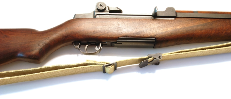
1 Lay your M1 Garand on its side with the muzzle facing towards your right, Op-Rod handle facing up. The bolt should be closed with the safety on as shown below.
2 If your M1 Garand has a sling attached remove it now.
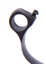
3 Grab the trigger guard behind the trigger and pull toward the butt plate. This will unhook the trigger guard latch and allow the trigger guard to pivot forward.
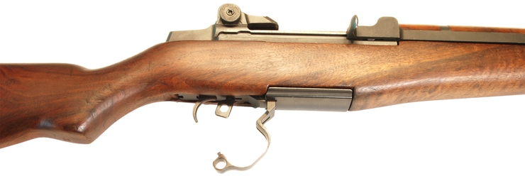
Sometimes the Trigger guard latch can be difficult to unhook. A piece of cleaning rod can assist you in pulling back on the trigger guard. The trigger latch hook can be seen in the image below.
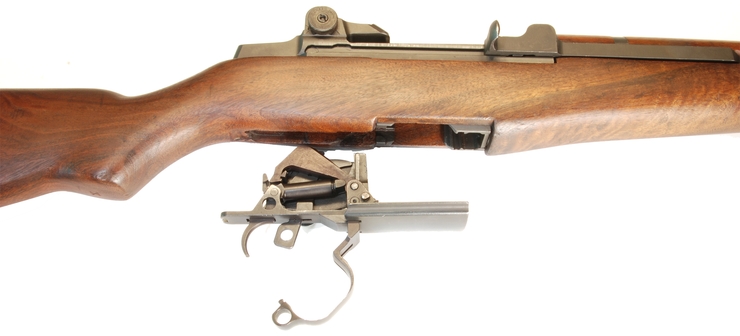
4 With the trigger guard unlatched, rotate the trigger guard until it is fully open as shown below.
5 With the trigger guard fully extended pull the trigger assembly straight out of the rifle.
6 With the trigger assembly removed rotate your M1 Garand so the trigger assembly well is facing up as shown below. Make sure your rear sight is lowered completely.
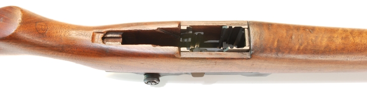
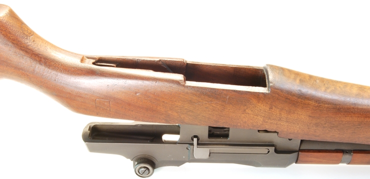
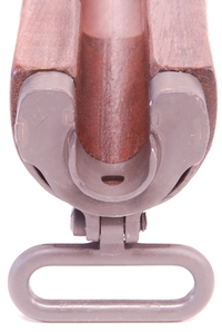
7 With your right hand hold the rifle at the front handguard forward of the sling swivel. Using the palm of your left hand lift up on the stock left of the trigger. The stock will pivot from the lower band and come free of the receiver. If your stock has a tight fit you may have to physically pull the receiver out of the stock.
A tight stock fit may be the most important factor in achieving good accuracy potential with your M1 Garand.
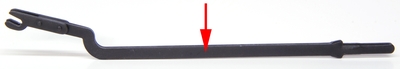
8 Pinch the follower Rod with your thumb and index finger as indicated in the image below. With a firm hold pull the follower rod back toward the muzzle compressing the op-rod spring and disconnecting the forks from the follower arm. When the forks are free you can lift up on the follower Rod and remove it and op-rod spring.
[Follower Rod]
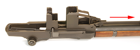
9 Using a suitable tool, push out the Follower Arm Pin. A small screwdriver or punch can be used.
The Follower Arm Pin can only be pushed out in the direction indicated below.
10 With the Pin removed. Pull out the Op-Rod Catch. Before you do notice how the Op-Rod Catch arm hooks under the clip release lever arm. When reassembling the M1 Garand later you’ll need to do this before reinserting the Pin.
11 The bullet guide sits in two notches in the receiver and should be removed toward the muzzle. Remove the follower arm at this time also.
12 Reach into the receiver and remove the follower assembly. Pay attention to the orientation of this part. On assembly, it’s possible to get this put in upside down if one isn’t careful.
13 Slide the Op-Rod back until the Op-Rod tab is aligned with the notch cut in the receiver. When it is aligned with the notch gently push the Op-Rod handle toward the notch. This allows the tab to clear the receiver channel. Gently pull the Op-Rod away from the receiver and rotate the Op-Rod handle. Slide it out from the Gas Cylinder.
NEVER force an Op-rod out of the rifle. The rod can be bent causing accuracy problems and other failures. The OP-Rod has two bends in it. These bends can be seen when looking at the Op-Rod from the side. Do not straighten your OP-Rod!
14 Slide the bolt forward and let it drop out of the receiver. You may have to rotate the bolt so that the firing pin tang clears the notch in the receiver bridge.
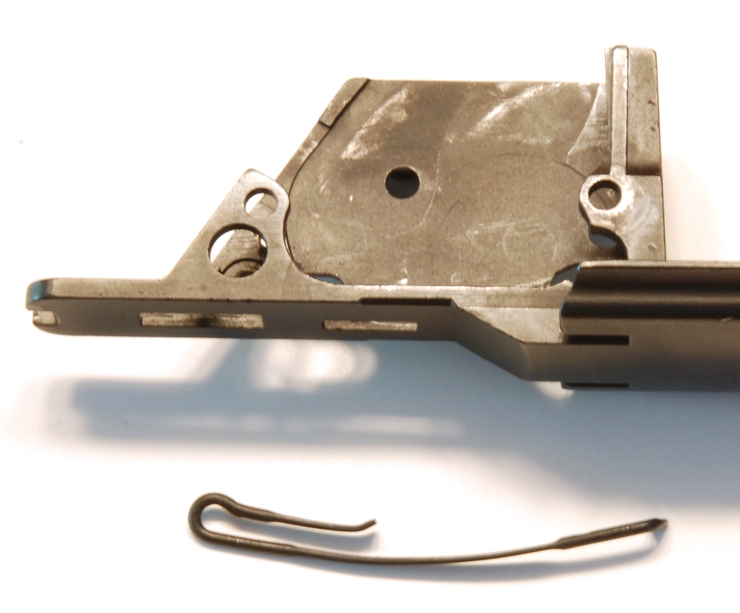
15 Lay the receiver on its side and press out the clip latch pin in the direction shown below. The clip latch spring will want to bind the pin as you remove it. To prevent this, depress the clip latch with your thumb and remove the pin. Once the pin has been removed the entire assembly can be pulled free from the receiver. When assembled the stock prevents this pin from sliding out during use.
The Clip Latch spring should be replaced when bringing an M1 Garand back into service. A weak spring can cause clips to be ejected early during firing.
16 Using a Gas Cylinder Wrench [Product Link] support the gas cylinder and unscrew the gas screw from the gas cylinder. A Gas Wrench is an important tool that prevents torque on the gas cylinder from transferring to the barrel splines. If the barrel splines become loose, the accuracy of the weapon decreases significantly.
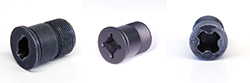
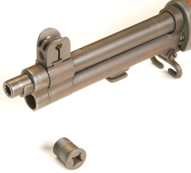
17 Unscrew the Gas Cylinder Lock Counter Clockwise when looking at the muzzle.
Stop here if you are performing a once-a-year teardown and inspection. The following steps should be performed during your initial weapon inspection, but only minimally thereafter. Removing the Gas cylinder and lower band frequently can degrade accuracy by loosening their fit. We’ll show you in another article how to tighten both if they’re already loose.
Going all the way:
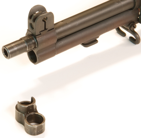
18 Slide the Gas Cylinder off the barrel by pulling it toward the muzzle. If the Gas Cylinder will not slide off freely you can tap on the bayonet lug to free it.
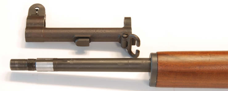
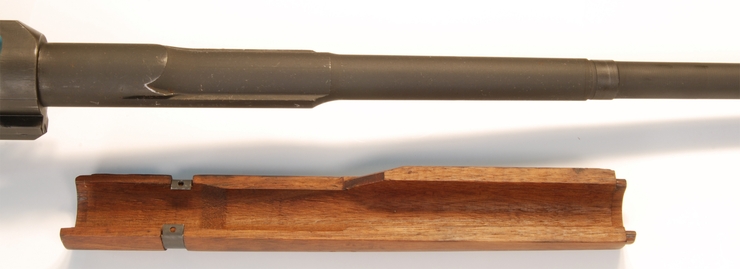
19 Slide the Front handguard off by pulling it toward the muzzle. Be careful not to damage the wood at the interface to the Lower Band.
We do not recommend removing the front handguard ferrule and spacer unless damaged. These parts require a special tool for re-installation.
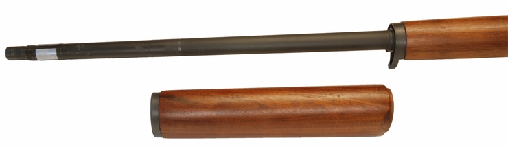
20 Place the M1 Garand on its side and locate the Lower Band pin. This pin holds the lower band onto the barrel. This Pin can be solid or the more common roll pin type. Inspect the lower band and determine if one end of the Lower band has been peened over. Sometimes the lower band pin can only be removed in one direction.
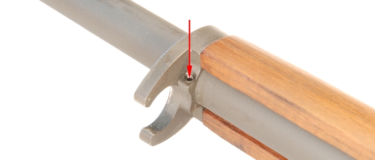
21 Using an appropriately sized punch tap out the lower band Pin.
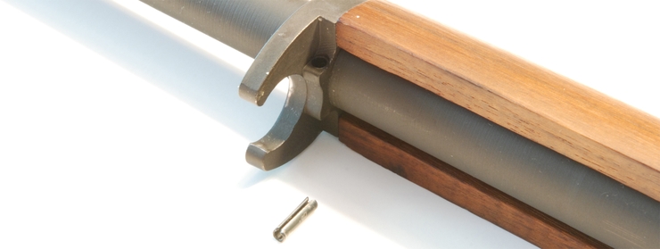
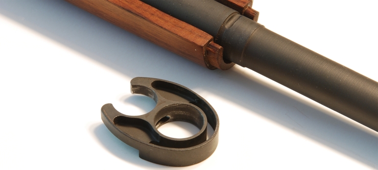
22 Using a non-marring tool tap on the Lower band on the ledge nearest to the Lower band Pin and drive the Lower band off the barrel.
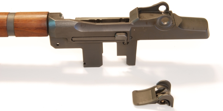
23 Carefully grab the rear handguard and slide it forward toward the muzzle until the retaining clip slides free from its barrel groove.
Be very careful with the rear handguard and clip. The wood is very thin and handguards crack very easily from mishandling. We do not recommend removing the rear handguard clip. The risk to the handguard doesn’t justify the effort. The clip should only be removed if it’s damaged or broken.
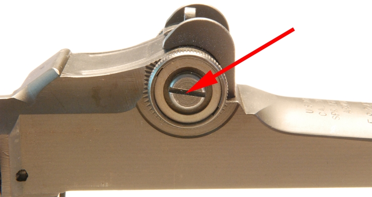
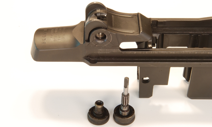
24 Rear Sight Removal. Start by grasping the elevation knob on the left side of the receiver and make sure the screw is not loose. Use an appropriate-sized standard screwdriver and turn it clockwise to tighten.
The elevation knob will want to spin while you are tightening the screw. Hold the knob with your free hand when tightening.
25 Using an appropriately sized standard screwdriver or the M1 Combination tool, turn the windage screw counterclockwise until it spins freely. The screw will remain captured in the knob when loose.
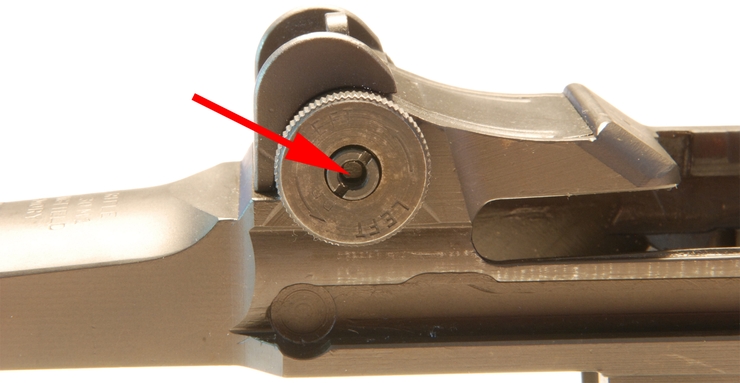
26 With the windage screw loose you can now remove the knob. Hold the elevation knob with your free hand and unscrew the windage knob counterclockwise until it comes free from the sight.

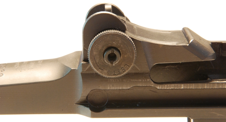
27 Slide the elevation knob and shaft straight out of the receiver.
When you re-assemble the rear sight, apply a thin coating of grease on the detents on the receiver where the knobs rotate. This will decrease the wear on the knobs and allow for a smooth sight adjustment.
28 Grab the rear sight and slide it out of the receiver. Slide the rear sight base back towards the heel of the receiver as shown below.
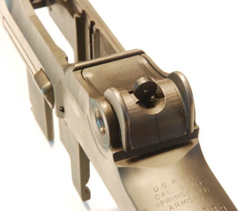
29 Using a wide standard screwdriver gently pry up on the rear sight base. This will cause the rear sight spring to pop out. Be sure to use a piece of cloth under the screwdriver to prevent it from marring the finish on the receiver when prying.
Stripping the Stock and Handguards:
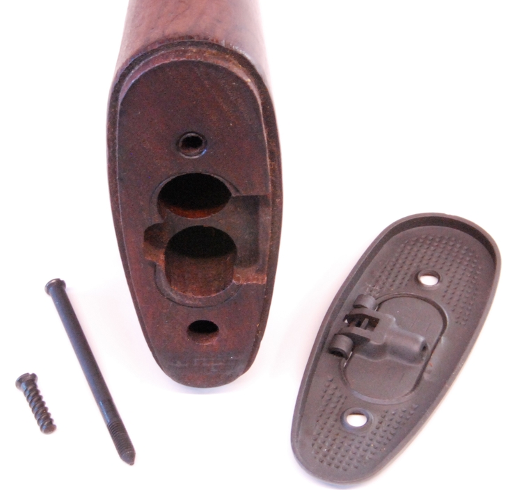
1 Using a wide standard screwdriver unscrew the two screws on the base of the butt plate and remove the buttplate from the stock. If the screws or the buttplate are stuck you can use some heat from a hairdryer or heat gun to help loosen them. Cosmoline can act as an adhesive in some cases. All screws on the M1 Garand are standard right-hand threaded.
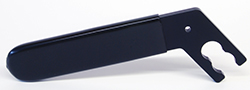
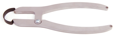
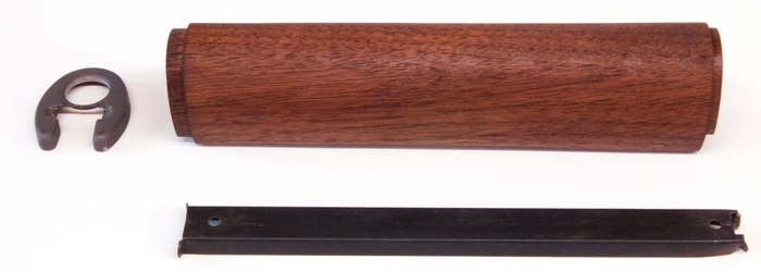
2 To remove the retaining clip from the rear handguard requires the use of a special tool. Attempting to remove the handguard clip without the pliers will almost certainly result in damage to the handguard or the clip. This clip should never need to be removed unless it is broken or the wood is being refinished. We’ve included the step here for completeness but this should not be attempted EVER without the tool. Follow the instructions that come with the tool to remove the clip.
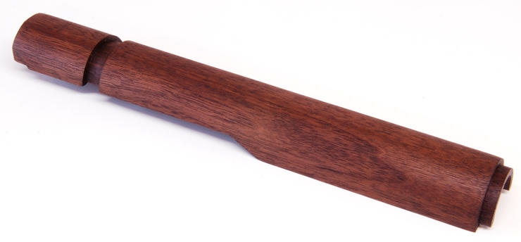
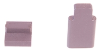
3 The front handguard contains a spacer and the front handguard ferrule. These parts were never designed to be removed once installed. The only reason to remove these is to refinish the wood or replace a broken part. These parts can be removed but at some risk to the wood and the parts themselves. To remove the spacer you have to bend back the Tabs holding the ferrule on and slide out the spacer. However, bending the tabs often damages the parkerizing and work hardens the bend. A special tool needs to be used to properly reinstall the spacer when finished. If you don’t have the tools to do this step properly we recommend leaving on the parts. The ferrule can sometimes be wedged on so firmly that damage to the wood occurs upon removal. If the ferrule doesn’t come off by hand, leave it on. Forcing it damages the part and often mars the wood in the process. The Spacer tool used during the installation of the liner is shown below with the spacer and ferrule.
4 The Front Swivel and Stock Ferrule can be removed from the stock if the wood is going to be refinished or the part is damaged. A tight stock ferrule is important to maintaining accuracy potential. Do not remove the ferrule unless you have to. On many M1 Garands, the screw holding the ferrule on has been staked and cannot be removed without damaging the part. If the screw doesn’t un-thread completely, leave it. If the screw can be removed then the swivel drops out and the ferrule can be eased off the stock. The ear’s on the ferrule when compressed cause a rib-like feature to form on the wood this helps the ferrule to grip the stock. Forcing the ferrule off will strip the embossed ribs off the wood and loosen the fit. The ferrule should be slowly and carefully rocked off the stock.
Stripping the Trigger Assembly:
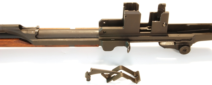
STOP! The trigger assembly must be de-cocked before continuing. Release the safety and make sure the hammer has fallen.
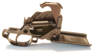
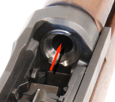
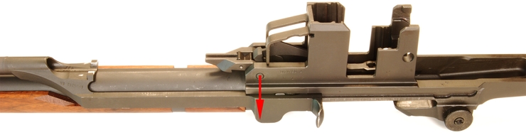
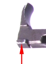
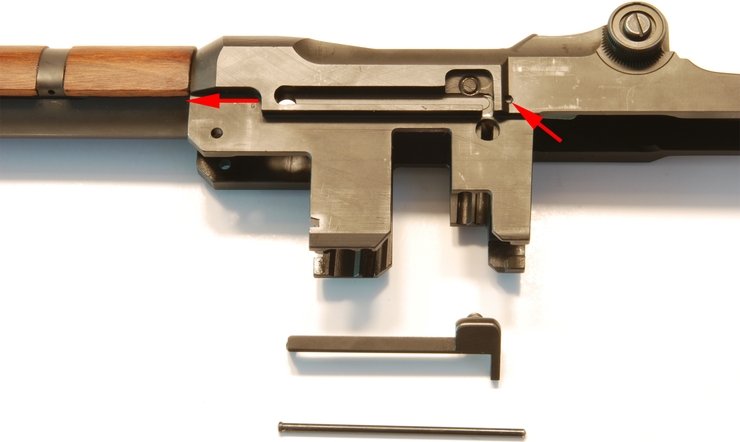
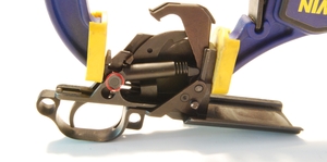
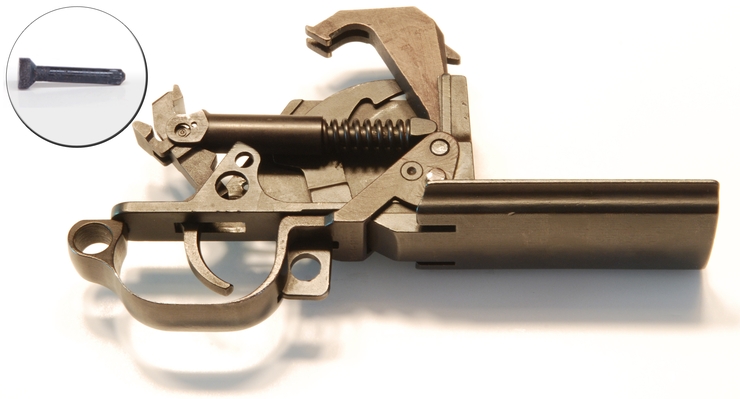
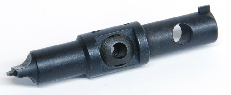
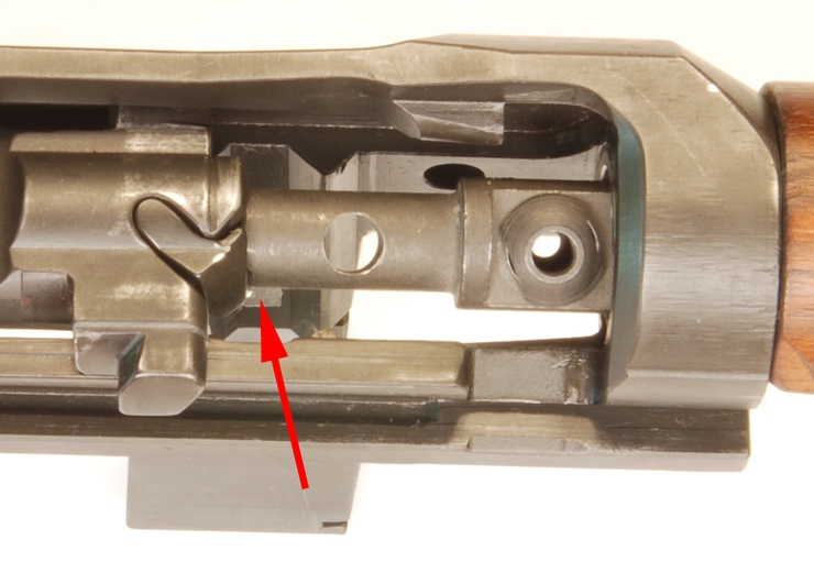
1 The back of the sear must be supported when removing the trigger assembly pin. The hammer spring places considerable force on this assembly. Failure to support the sear can result in parts being ejected with considerable force. Put on a pair of safety glasses before continuing. The sear can be supported with your hand or a tool may be used as shown below.
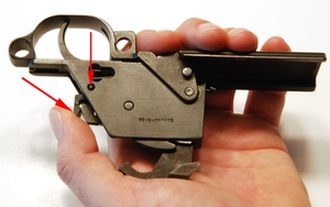
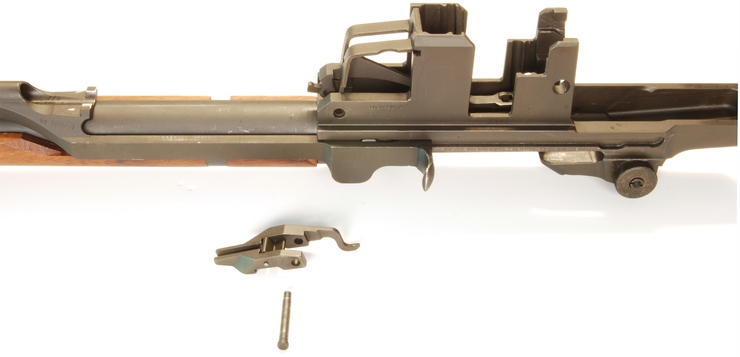
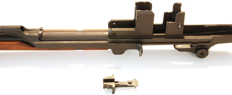
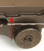
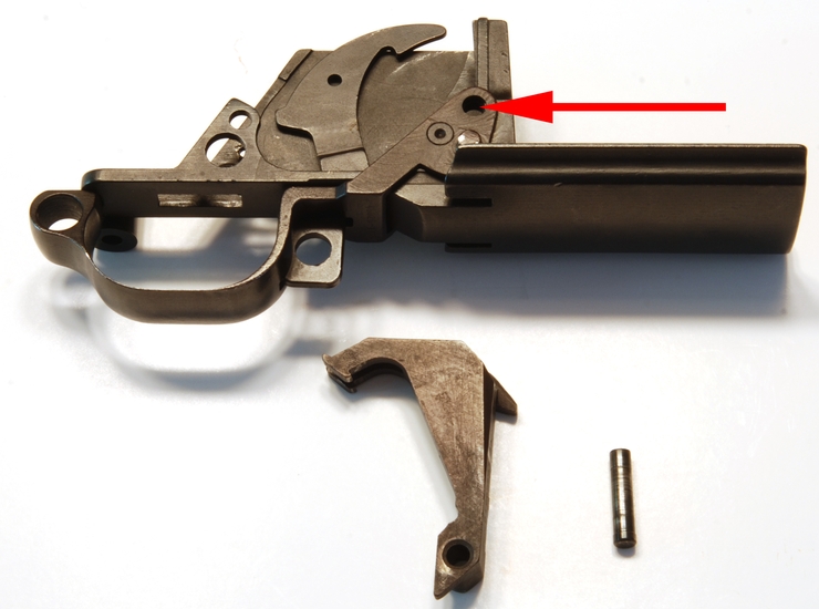
2 Using a punch press out the trigger pin (see image above for location marked in red). This pin can only be removed in one direction as shown by the arrow in the upper left image. This pin often pops out with considerable force. Be sure to have a backdrop that will catch the pin. With the pin removed, release your grip on the sear and allow the trigger spring to decompress. The photo below shows the correct alignment of the sear, trigger, hammer, and spring assembly required during reassembly.
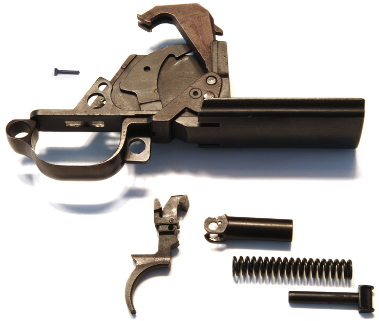
3 Remove the Sear/Trigger, Hammer Spring, Housing, and Plunger from the trigger assembly.
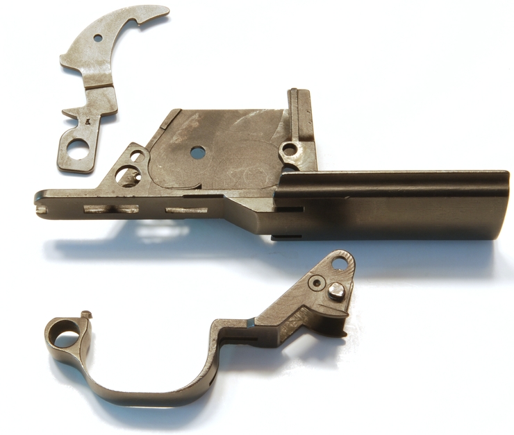
4 Press out the Hammer Pin, freeing the trigger guard and hammer. This pin is removed in one direction only. One end of the pin is larger in diameter than the other.
5 Remove the safety by gently prying it from the trigger housing. The safety is snapped into place with a small stud on its side. Next, remove the trigger guard. Slide the guard aft slightly then rotate and pivot the part allowing for its removal.
6 Using a non-marring tool push out the clip ejector spring.
There are several part assemblies that should not be broken down further. Those assemblies are the trigger/sear, windage knob, and follower assembly. There are no serviceable parts in these assemblies. The front sight can be removed from the gas cylinder if it needs to be replaced. Moving the front sight will effect the point of impact significantly.
Stripping the Bolt:
STOP! The bolt assembly contains two springs compressed under significant force. Always wear eye protection when disassembling the bolt.
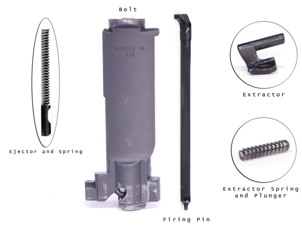
The bolt on the M1 can be dissassembled by hand using the M10 multi-tool or with a bolt tool sold by the CMP. We’ll show you how to use both. If you own several M1’s then the bolt tool becomes a time saver and makes the job effortless. Shown below is an M1 bolt completely stripped with all its parts.
Using the CMP Bolt Tool:
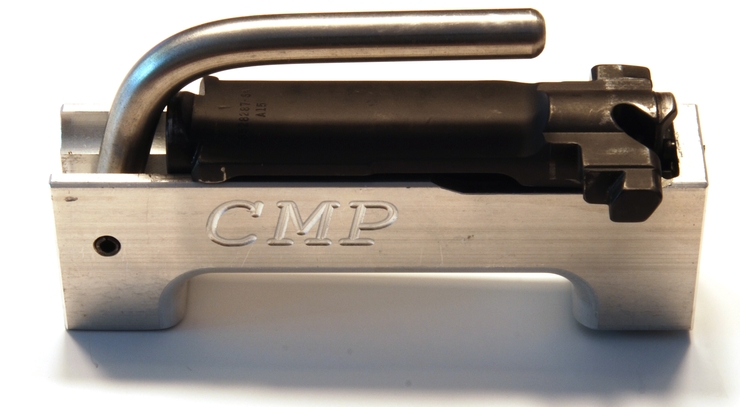
1 Lift the compression handle on the tool and insert the bolt. Orientation of the bolt should be as shown below.
2 Using your left hand squeeze the handle of the tool against the bolt causing the compression of the ejector and spring. With your right-hand press the extractor removal button on the bottom of the tool causing the extractor to be pushed up from the bolt. Grab the extractor and remove it. Release the button.
Be sure to release the tool button before releasing the handle. If you fail to do this then the tool button pin will get pinched in bolt. Squeeze the handle again and release the button pin.
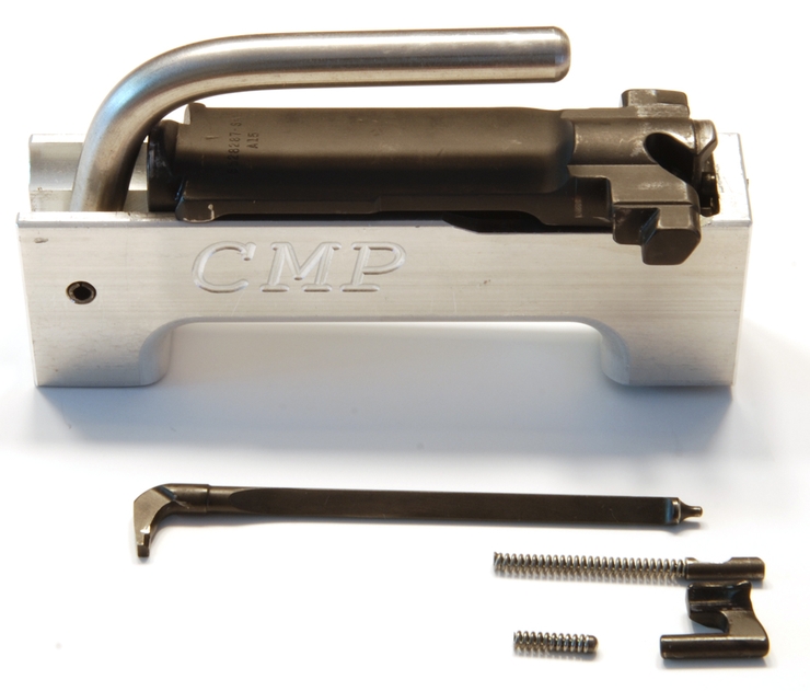
3 Release the handle and allow the ejector to decompress slowly and completely. Remove the bolt and pull out the extractor spring assembly and the ejector spring assembly. The firing Pin slides straight out the back of the bolt.
4 To re-assemble the bolt with the tool you need to reverse the process. The most critical part is to make sure the orientation of the ejector is correct allowing the extractor to snap back in place. Re-insert the firing pin, ejector assembly, and the extractor spring assembly into the bolt. Place the bolt back on the bolt tool and compress the ejector spring by squeezing the handle on the tool. Snap the extractor back into the bolt from the top. When the extractor is seated you may release the handle of the tool.
Using the M10 Multi-Tool:
Apply a thin layer of grease to the surfaces of the M10 tool that will come in contact with the bolt face and barrel shoulder. This will reduce wear on the finish when the tool is rotated under load.
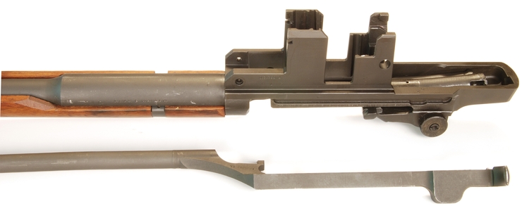
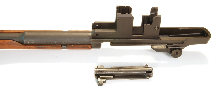
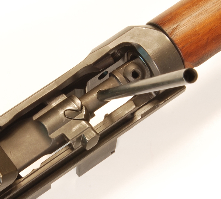
1 retract the bolt and op-rod until it locks fully back. Insert the M10 tool into the chamber (Flat screwdriver end first). Orient the tool such that the small lug on the M10 tool is under the extractor (see image below). Slowly release the bolt and ease it onto the tool. (DO NOT SLAM the bolt onto the tool!).
(Op-Rod removed to show proper M10 tool alignment.)
2 Insert a segment of the cleaning rod into the hole in the M10 tool. This will be the lever arm allowing you to rotate the tool and remove the extractor.
3 Cup your left hand over the top of the bolt to catch the extractor as it pops out. Push the OP-Rod forward holding the bolt against the tool and rotate the M10 tool counterclockwise until the tool lifts up the extractor. The extractor may pop out with some force.
4 Slowly pull back on the bolt and remove the extractor spring plunger assembly and the ejector assembly. The firing pin can also now be removed from the bolt.
5 To re-assemble the bolt, install the firing pin, ejector assembly, and extractor spring and plunger assembly back into the bolt. Verify the orientation of the ejector is correct before continuing.
6 Rotate the M10 tool back to its original position. Push the op-rod forward causing the ejector spring to compress. With the ejector spring compressed press the extractor back into position.
7 Retract the bolt fully and remove the M10 tool from the rifle.
Congratulations!
You’ve just successfully performed a detailed strip of your M1 Garand. To re-assemble your M1 Garand follow these instructions in reverse. Before you do be sure to read the section on part cleaning, inspection, and Improvements. You’ll want to read the section on lubrication before re-assembling the rifle.