
M1 Garand Inspection
Every M1 Garand should be stripped down, cleaned, and inspected before its initial use. This article is intended to show you what parts need to be inspected and how to determine if they’re still serviceable. A thorough inspection is the only way to determine what condition your M1 is in. Performing this step will save you from having to diagnose malfunctions in the field. This article is designed to cover the basic safety features that must be in spec before the M1 Garand is used. We’ll also show areas that are prone to wear or failure. This article should not be used as a replacement for a safety inspection by a certified armorer.
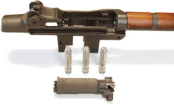
If your M1 Garand is still assembled, please go here [Strip your M1 Garand] and perform a detailed strip of the rifle. This article assumes the parts to be inspected have been removed from the rifle.
You’ll need a couple tools to properly measure several of the parts we’ll discuss below. A good micrometer and a quality set of calipers will be required to measure part dimensions. When possible use the micrometer to get the most accurate measurement.
The Receiver:
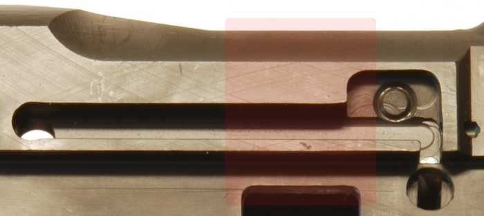
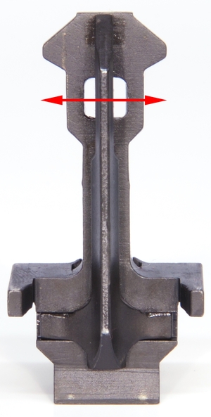
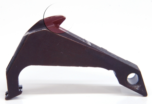
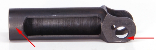
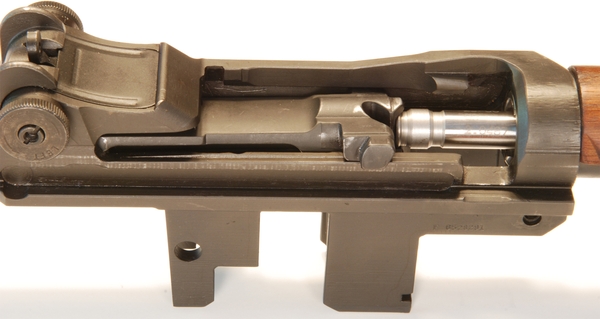
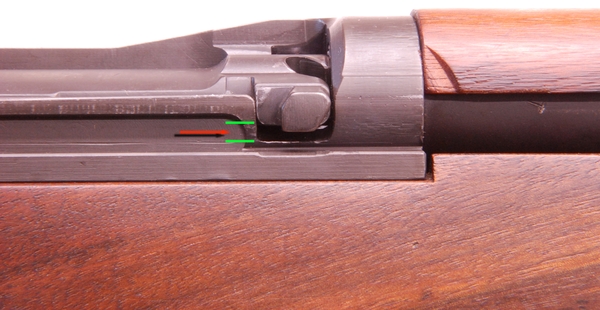
1 The first part of the M1 Garand we are going to inspect is the receiver. The receiver is the foundation of the rifle and on the M1 Garand, there are several areas we want to look closely at. the first area we are going to inspect is called the bridge. As the name implies it is the piece of metal that bridges the two sides of the receiver about midway down. The bolt rides through the hole in the bridge. If you look closely you’ll notice a notch and a ramp cut out in the bridge. This is a critical safety feature on the M1 Garand. This area is designed to prevent the firing pin from striking the cartridge until the bolt has cammed shut and the firing pin aligns with the notch in the receiver. As the bolt begins to close, the ramp (Right Arrow below) on the bridge pulls the firing pin away from the primer. When fully closed (in battery) the firing pin aligns with the notch and allows the bolt to strike the firing pin tang. Verify that the bridge is not cracked and the ramp is in good condition.
Inspect the heel of the receiver for any signs of cracks. The heel of the receiver is around the serial number of the rifle.
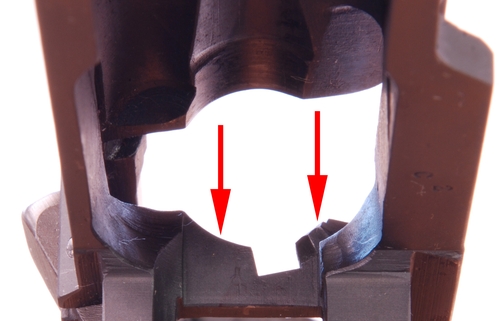
(View from the bottom of the Receiver Bridge)
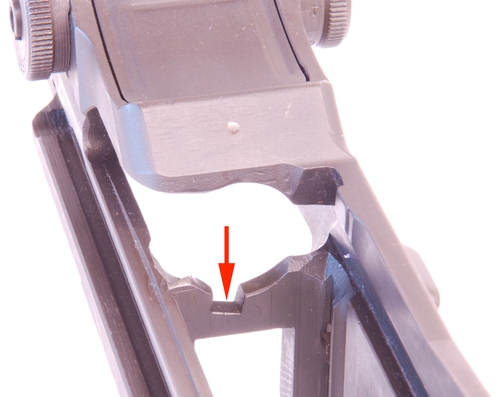
(View from the top of Receiver Bridge)
A simple way to test a suspected crack is to saturate the area with kerosene or mineral spirits, then quickly wipe dry the surface. If a crack exists then the solvent will weep out of the crack leaving a glossy line at the crack location. Spray dies to detect cracks can also be purchased at your local auto supply store.
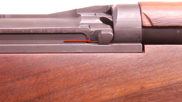
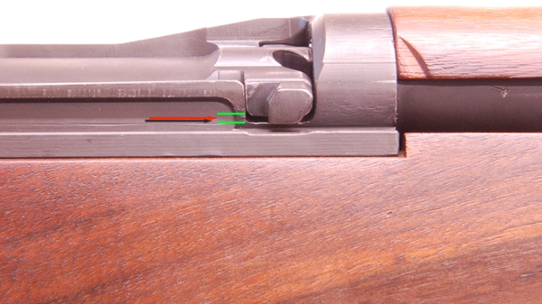
2 Next insert the bolt in the receiver without the op-rod attached. Slowly rotate the bolt into battery and verify that the firing pin is retracted as the bolt closes.
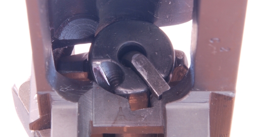
(Firing pin retracted when not in battery)
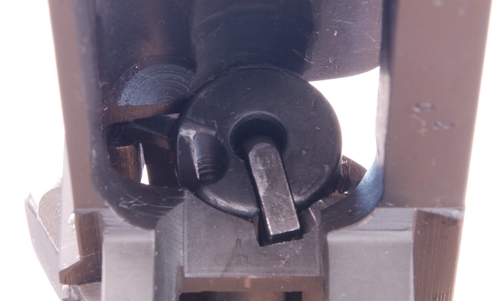
(Bolt in battery. Firing Pin aligned with the notch in Receiver Bridge)
3 Beware of the welded receiver! If you bought your M1 Garand from the CMP or its predecessor the DCM then you can skip this section. If you bought your M1 Garand from someone else, you’ll want to inspect your receiver carefully. Sometime during the 1960s and 1970s de-milled M1 Garands were purchased as scrap. The two cut halves were welded back together. Some of these receivers are still in circulation today and should be considered wall hangers, and never fired. The image below, highlighted in red, is the area you want to pay particular attention to. The receiver shown below is NOT a welded receiver but shows the normal type of machining marks you should see. Below is a quick list of things to verify.
(A good Springfield receiver with normal machining marks and wear)
- The machining marks across the entire zone should be consistent
- Edges should be sharp and straight with no steps or misalignments.
- The drawing number on the receiver should be correct for the serial number.
- Discoloration or weld marks should not be present.
- Missing machining marks or evidence of blasting is often a sign of a welded receiver.
- Inspect the heel of the receiver for cracks or welds. The heel is the area containing the serial number.
If you have any suspicions about your M1 Garand, have a gunsmith inspect it before using it.
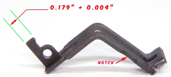
4 The bullet guide is a very important and often overlooked part of the M1 Garand. Having nothing to do with guiding bullets, this part sets the timing for releasing the op-rod catch when a clip is inserted. The bullet guide also acts as a strength member for the receiver legs. Two versions of this part have been produced. The new part can be quickly identified by the notch cut into the side of the part. The critical dimension on the bullet guide is shown below (known as the Accelerator Cam Surface) as 0.179″ + 0.004″. Older bullets guides do not have the notch on the side and will measure 0.175″ + 0.004″. If your M1 is having timing issues check your bullet guide.
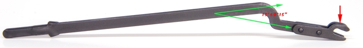
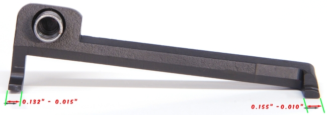
5 The follower Rod should be inspected and the forks examined for cracks or breaks. The forks are indicated with the arrow in the image below. The base angle (15°±0°15″) for the follower rod is shown below. Replace the rod if damaged or out of spec.
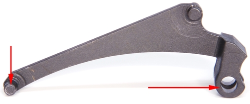
6 The follower arm should be inspected in the areas indicated in the photo below. Replace the follower if any cracks or broken lugs are found.
7 The follower and follower slide assembly should be inspected for cracks or chips. The slide should move freely back and forth in the follower. Leave the slide and follower assembled unless service is required. Oil the slide if it doesn’t move freely and inspect for damage.
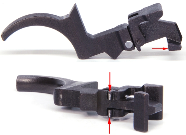
8 The operating rod catch is a critical component to the correct operation of the M1 Garand. Thankfully, this part is fairly robust and rarely needs to be replaced. The areas you will want to inspect are highlighted below. Pay attention to the Cam arm, accelerator, and the operating rod catch. The operating rod catch should have a smooth radius and be free from burrs or chips. If this area is rough the op-rod may fail to release when a clip is inserted. The accelerator is the area that the bullet guide acts on. The accelerator should be able to rotate around the pivot freely within its designed range of motion. Finally, inspect the Cam arm for chips or burrs.
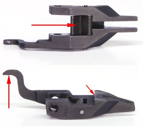
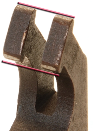
9The clip latch is often overlooked when diagnosing problems. The clip latch has two lugs. One lug engages the op-rod catch and the other engages the clip when inserted. Pay attention to the lug that locks the clip in place. This lug can become worn and fail to properly lock the clip in place. The lugs should be square with well-defined edges. The basic lug dimensions are shown below.
10The lower band interfaces with the stock ferrule and is pinned to the barrel. It should be a tight fit on the barrel and may need to be driven off and onto the barrel. A loose lower band will degrade the rifle’s accuracy potential. When the rifle is installed inspect the lower band / ferrule / op-rod interface for signs of binding or rubbing. This area is the most common area for issues to arise. Performing the tilt test (See below) is the best way to determine if you have an interference issue.
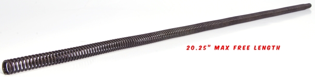
11The operating rod spring is probably the single most critical component to the proper cycling of your M1 Garand. The op-rod spring connects to the follower rod and slides inside the op-rod tube. This spring provides the force required to properly cycle the rifle. Many M1 Garands are shipped with springs that have seen significant service and need to be replaced. Your first purchase for parts should always include a new op-rod spring. It is hard to determine if an op-rod spring is still serviceable. Measuring spring length alone doesn’t tell us if the spring constant has changed in the past decades of service. Due to the length, a special jig is required to prevent buckling when testing the spring. You can purchase new replacement springs cheaply [Here] and should do so when putting an M1 Garand back into service. Remember to grease the op-rod spring when re-installing.
12 The operating Rod, also known as the Op-Rod is responsible for converting gas pressure in the gas cylinder into a force that is used to cycle the bolt. It also works in conjunction with the operating rod catch to lock the action open when the rifle is empty. The long tube section of the Op-Rod has two very subtle bends in it. This is by design. If you sight down the op-rod from the TOP it should appear straight. If you sight down the op-rod from the side the two bends should be visible. Never attempt to straighten your op-rod. To determine if the op-rod is correctly formed it must be mounted to the rifle and inspected for binding.
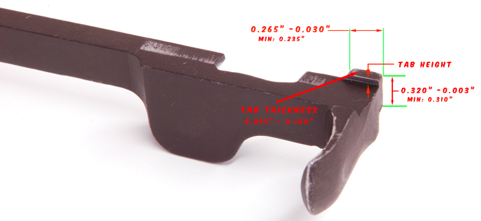
The op-rod has several areas that need to be inspected. Start with inspecting the op-rod tab. The tab is the area that most often has wear issues. As the tab wears out it may fail to stay in the receiver track and dismount during firing. The tab should be square with dimensions, not less than the minimums as shown below.
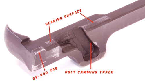
Next, we want to inspect the bearing surfaces and the cam track. The op-rod acts on the bolt lugs at this location. It is normal for the bearing surface to show wear on the parkerizing. Inspect the bearing surface for any deep grooves or abnormal wear. Check the bolt cam track for signs of chipping or uneven wear.
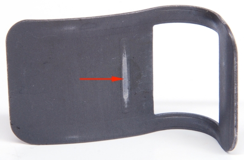
13 Next we want to inspect the rear sight spring. The spring has a tab stamped in it that acts on the rear sight. When this tab wears down the rear sight becomes loose and shot to shot accuracy suffers. With the rear sight extended approximately halfway, attempt to wiggle the rear sight aperture. If the rear sight is loose inspect the sight spring for wear. The area you want to inspect is shown below. Rear sight springs are not expensive and should be replaced when worn.
Before installing the spring, apply a thin layer of grease to the spring as shown below. Doing this will reduce the wear on the part.
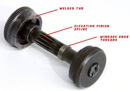
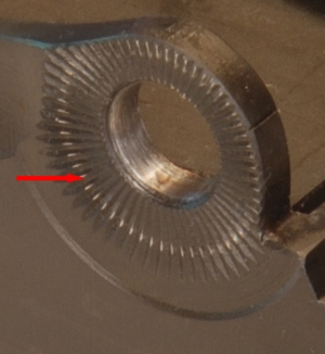
14 With the rear sight dissembled start by inspecting the elevation knob. On the inside of the knob, you should see a tab. This tab should be sharp and well-defined. As this tab wears down the positive detents of the elevation knob will become weaker. Some of these elevation knobs have been repaired by welding a new tab as shown below. Replace the knob should you come across one. Inspect the pinion, spline, and windage threads for damage or significant wear. USGI and reproduction sight components are still widely available.
Finish your inspection by examining the serrations on the receiver. The serrations should be sharp and crisp. Apply a thin layer of grease to the serrations before reassembly to reduce wear.
Inspecting the Bolt:
The bolt on the M1 Garand has several areas that we’ll want to inspect prior to use. The bolt has several integral safety features that must be operational to safely fire the rifle. These features make sure the rifle is in battery before the firing pin is allowed to strike the cartridge. We’ve previously discussed the firing pin bridge above in the receiver section.
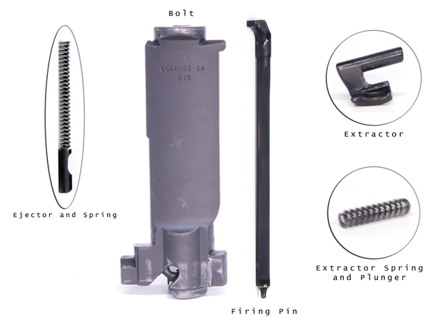
1 A disassembled bolt is shown below with all its sub-parts. If you haven’t stripped your bolt yet be sure to read the article on doing so here: [Link to Article].
2 The first part that you’ll want to inspect is the firing pin. On the M1 Garand, the firing pin is free-floating. It should move freely inside the bolt. It is normal for the firing pin to slightly dent the primer when a round is chambered. The firing pin does not have enough kinetic energy to fire the primer and this process does not pose a safety hazard. For this to be true the firing pin must move freely and not be stuck in the bolt. Old grease or cosmoline can jam a firing pin causing a safety hazard. Always disassemble and clean the bolt before you fire your M1 for the first time. A few drops of oil spread over the surface is all the lubrication required for the firing pin.
Start by inspecting the firing pin tip. The tip of the firing pin that strikes the primer should be free from chips or burrs and should be straight. It’s normal to have the parkerzing worn in and around the firing pin. This is not indicative of a problem and is considered normal wear. The surface should be smooth and not pitted from rust.
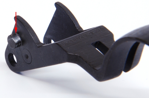
3 Next inspect the firing pin tang. This is the part of the firing pin that is struck by the hammer. This part of the firing pin is the most commonplace for a break to occur. Check the tang for chips, cracks, or abnormal wear. The tang works with the receiver bridge to retract the firing pin as the bolt goes into battery. If the tang is worn or broken this critical safety feature may not function properly. The firing pin should be replaced if it fails inspection.
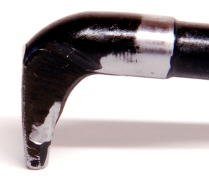
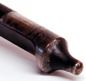
[This worn firing pin is nearing the end of its service life]
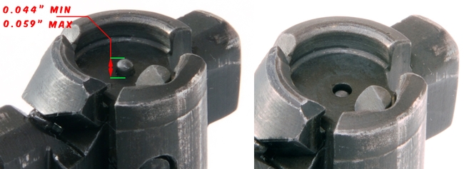
4 We next want to measure how far the firing pin protrudes from the bolt face. Push against the firing pin tang until the firing pin extends fully above the bolt face. Measure the height from the bolt face to the tip of the firing pin. The firing pin should extend between 0.044″ and 0.059″ above the bolt face. When retracted the firing pin should be completely below the face of the bolt as shown in the image below on the right. With the firing pin retracted inspect the hole in the face of the bolt for chips or damage. The firing pin must move freely.
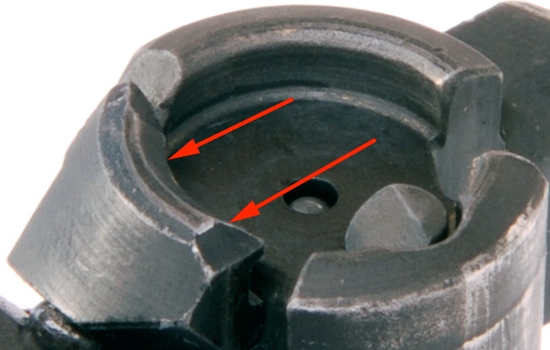
5Next we’ll inspect the locking lugs on the bolt. The locking lugs are circled and highlighted below. Both of the bottom lugs should show signs of wear on the locking surface. We’ll discuss how to lap the bolt lugs in another article to improve lockup. It’s important that both lugs make contact with the receiver when in battery. Check for cracks or chipping on the lugs. The rear lug is shown circled in the middle of the image below. This smaller lug should be free from burrs or signs of abnormal wear. If the bolt doesn’t slide freely in the receiver check the rear lug for signs of binding. Adjacent to the rear lug is the slot where the hammer nose cams the bolt shut. It’s normal for the parkerzing to be worn in this area. However, there should be no chips or burrs present.
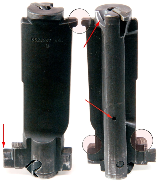
6 Another important area to inspect on the bolt is the operating rod camming lug. This lug is shown in the image above (left side bottom arrow). The op-rod uses this lug to cam the bolt open and then retract the bolt. This lug should not have abnormal wear or chips missing. The little hole on the bottom of the bolt connects to the ejector spring. With the bolt assembled place a drop of oil in this hole.
7 The last part to inspect of the bolt assembly is the extractor. The extractor’s job is to grip the base of the cartridge and extract it from the chamber when the bolt is retracted. Verify that the lip on the extractor isn’t cracked or badly worn. If your M1 Garand is failing to extract cartridges inspect this part and the associated spring carefully. The area between the bolt locking lug and the extractor must be clean and free of foreign material. If material accumulates in this area the extractor can fail to snap over the cartridge preventing the bolt from going into battery.
Inspecting the Trigger Assembly:
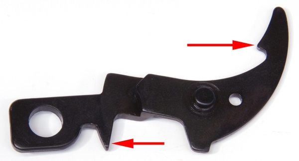
1 We’re next going to inspect the hammer. The hammer on the M1 Garand should be inspected carefully. There are several areas that need to be in spec before we can safely use the hammer. We’ll start with the camming lug. The camming lug provides an important safety function. It forces the bolt to lock closed if the bolt is slightly out of battery. If the bolt is only marginally closed, the camming lug will impact the rear of the bolt preventing the hammer from striking the firing pin. If this feature is damaged or missing it’s possible for your M1 Garand to fire out of battery. The cartridge will rupture and likely turn your M1 Garand into a pile of splinters and mangled parts. The image below has highlighted the camming lug on the hammer.
- The camming lug must be present and not broken or missing.
- The camming lug should not have large chips in it.
- Look for cracks or other signs of abnormal wear.
- Missing parkerizing is normal from use and doesn’t indicate a problem.
2 We next want to inspect the hammer hooks. These hooks allow the hammer to engage the trigger/sear assembly. One set of hooks on the hammer engages the sear when the trigger is pulled rearward and the bolt cycles the hammer back after firing. When the user releases the trigger, the sear transfers the hammer to the second set of hooks. If the hooks are broken or badly worn then the hammer can follow the bolt home and fail to engage the sear. Broken or badly worn hooks can also allow the hammer to fall without a trigger pull, causing the rifle to discharge.
It’s normal to see some wear on the hooks and very slight rounding of the corners (see lower left hook below). Inspection of the hooks as they engage the sear is always necessary to determine if the hammer is safe to use. Each of the two hammer hooks must be engaged on the sear when latched. The hammer is an item that has a limited service life and should be replaced when the wear becomes excessive or unsafe.
3 On the side of the hammer is the safety engagement area. Make sure this part of the hammer is free from burrs or other damage that would prevent the safety from engaging.
4 The trigger guard provides three main functions on the M1 Garand. The first is to protect the trigger. The second is controlling the lock-up of the rifle. The third is a way to manually cock the hammer; should it be necessary. Trigger guards come in two designs. The older design is the milled trigger guard as shown below. The second is the stamped trigger guard seen in later years. Both trigger guards have lugs that lock into the receiver and apply the clamping force needed to hold the rifle together. A tight lockup is one of the most important factors in maximizing the accuracy potential of your M1 Garand. With time the lugs wear and develop a flat spot which reduces the lock-up force (see below). If the trigger guard latches too easily or unlatches during firing you will want to replace the trigger guard. Trigger guards are fairly inexpensive and the newer stamped design has lugs that can be replaced. Be sure to also inspect the hook at the end of the trigger guard, if it is broken or worn it won’t stay latched.
5Next inspect the safety. The safety should be free from cracks or chips. The arrows in the image indicate areas that you should inspect. If your safety is damaged it should be replaced, there are no acceptable repair methods for this part.
6The hammer spring housing is a thin part and prone to cracking. Areas that are prone to cracking or breaking are shown below. Replace the housing if any cracks or damage is found. Inspect the hammer spring for broken links and replace if needed. Finally, inspect the hammer plunger and make sure there are no burrs on the nose. This is the area that interfaces with the hammer.
7 The trigger and sear assembly as shown below must be undamaged and free from chips or cracks. The arrow in the bottom photo is the surface that the hammer hooks slide on and latch the sear. This area should be smooth with a sharp edge. Wear marks from the hammer hooks is normal and doesn’t indicate a problem.
The bottom image shows two areas that often crack or break on the trigger/sear assembly. If any cracks or chips are found in these areas the assemble must be replaced.
New springs are available and affordable. We recommend purchasing a spring kit for your M1 Garand if the rifle has not be in service for several years or decades. Incorrect spring forces are probably the top cause of malfunctions in the M1.
Trigger Assembly Safety Test:
The following safety test should be performed whenever you break down your trigger assembly, and before you fire an M1 Garand for the first time.
- Remove the trigger assembly from the rifle. Close and lock the trigger guard.
- With the hammer dropped, pull back firmly on the trigger and don’t release it. Manually cock the hammer back until it engages with the sear. Let go of the hammer (The hammer must not fall).
- If the hammer does not fall, grab it firmly and pull on it. (The hammer must not fall)
- If you pass the first test, very slowly release the trigger while watching how the sear transfers from one set of hammer hooks to the next. (The hammer must not fall).
- If the hammer does not fall release the trigger completely.
- Pull the trigger and the hammer should fall.
- Cock the hammer again. Engage the safety. Pull the trigger firmly. (The hammer must not fall).
Barrel Inspection
Before you begin with the barrel inspection it’s important that the barrel be thoroughly cleaned. Previously used M1 Garand’s often have barrels with years of fouling in them. You’ll want to clean the barrel until all the powder and copper fouling has been removed. You can read the article on cleaning here: [Cleaning your M1 Garand].
1 Verify that there are no barrel obstructions and the rifle is unloaded. This should have been performed when you cleaned the barrel for the first time. With all the wood removed do a general inspection of the barrel. Sight down its length for any signs of obvious bends or bulges. If the barrel fails this basic inspection it should be replaced and not fired.
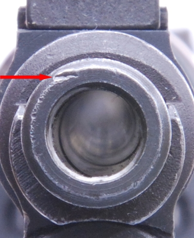
2 Next inspect the muzzle end of the barrel. Inspect the threads on the end of the barrel. These threads are used by the gas cylinder lock to secure the gas cylinder to the barrel via the gas screw. These threads (indicated by the arrow in the image below) should be sharp and undamaged. If the threads are worn or damaged then the gas cylinder may become loose during firing.
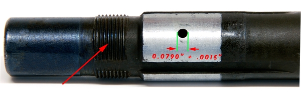
3 The next item to inspect is the gas passage. The gas passage is a hole drilled in the barrel as shown above. Its function is to allow gas to flow into the gas cylinder; facilitating the cycling of the rifle. The dimension of this hole is important and should be checked prior to use. If the hole is fouled with carbon, insufficient gas flow will cause short stroking of the rifle. If the hole is too large, excessive pressures can develop causing damage to the op-rod or receiver heel.
An easy way to inspect the gas passage is to purchase two numbered drill bits from your local hardware store. You want to purchase a #47 and a #46 drill bits. These will become our GO and NO-GO gages respectively.
The #47 drill bit should fit into the gas passage. If the gas passage is fouled, gently spin the drill bit with your fingers as you clean the passage. DO NOT USE A POWER TOOL. After the passage is clean, take the #46 drill bit and using the smooth end (not the drill end) verify that the drill bit will not fit into the gas passage.
Depending upon when your barrel was manufactured it may or may not have the chromed pads between the barrel splines. This was originally done to prevent corrosion when shooting corrosively primed ammunition.
4Inspect the crown of the barrel for dents or signs of abnormal wear. The end of the barrel is often subject to abuse and can greatly affect the accuracy potential of the rifle. There are several profiles that can be machined into the end of the barrel. Most on the M1 will be the GI profile as shown below. Dents that don’t intersect with the bore usually don’t affect the accuracy.
Pay special attention to dents or marks that intersect with the lands or distort the exit profile. There are tools available to re-cut the crown of the barrel if it is required.
Gas System Inspection:
The M1 is a gas-operated rifle. The gas system needs to be inspected to ensure that the rifle will cycle properly. When a cartridge is fired, gas flows from the barrel into the gas cylinder. This process pressurizes the cylinder. This pressure generates an impulse on the operating rod which cycles the bolt. As the bolt is forced rearward the old cartridge is ejected, the hammer is re-cocked and a new cartridge is fed.
To determine if your gas system is still in spec you’ll need a couple of tools. First, you’ll need your micrometers or a set of calipers. You’ll also want to get two gage pins. The gage pins are used to determine the wear inside the gas cylinder in the area of the power stroke. We sell a gage pin set for this purpose. Our gage pins are manufactured to high precision and are NIST calibrated. You can purchase the set of pins here. [Link to Product]
When re-assembling the gas cylinder onto the barrel, verify that the gas passage is centered in the small cutout in the gas cylinder.
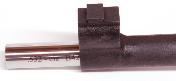
1Start by taking your gage pins and making sure they are clean and free from any protective grease or other films that might change their dimensions. You’ll also want to clean the inside of the gas cylinder thoroughly. Any carbon film or other residue will affect the measurement. The two gage pins that are used are shown below.
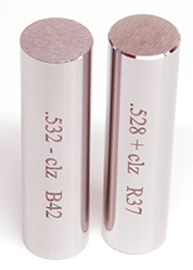
The 0.528+” pin is the GO gage pin and the 0.532-” pin is the NO-GO.
You can purchase a set of GO/NOGO Gages in the online Store. [Link]
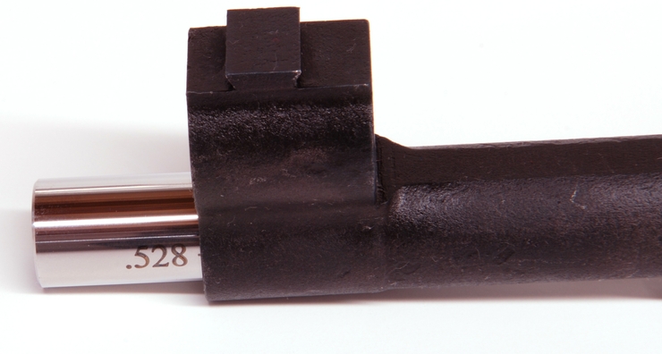
2With the gas cylinder cleaned first insert the 0.528″ pin. Insert the pin from the threaded end of the gas cylinder. This pin MUST slide freely through the gas cylinder. If the pin does not, make sure all the carbon fouling has been removed from the cylinder and try again. If the gas cylinder still does not accept the 0.528″ pin it should be replaced. Another test you can perform with the 0.528″ pin is to check to see if the gas cylinder is out of round. With the pin inserted shine a bright light from the opposite end of the gas cylinder. Look for any light escaping around the edge of the pin from the opposite side.
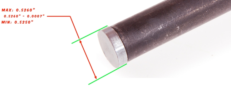
3Next insert the 0.532″ pin into the gas cylinder. This pin should slide in just past the threaded area and then stop as shown below. If the pin is able to be inserted more than 0.5″ past the threaded area then the gas cylinder has reached its end of service life. When the rifle is fired the entire power stroke occurs within the first half-inch of the gas cylinder. When the cylinder diameter has increased such that a 0.532″ pin can be inserted, the cylinder has reached the end of its service life. In this condition, too much gas is lost during the power stroke. This loss of pressure can lead to the rifle’s short stroking and general failures to cycle.
4 You next want to measure the gas piston on the end of the operating rod. This piston is the surface that the gas pressure is applied to. The dimensions for the gas piston are shown below. Be sure to remove any powder fouling from the piston before taking your measurements. Measure the gas piston with your micrometer or calipers at several places around its circumference. Verify that the gas piston is not out of round.
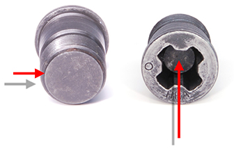
5The last item to check is one that is often overlooked. The USGI gas screw comes in two forms. The solid screw has a single slot on the end. The more common gas screw has an internal poppet valve and is used in conjunction with the grenade launcher. This poppet valve often is full of dirt and sand and can cause the valve seat to leak. The valve seat is shown below and left. Using a punch or other device, grasp the gas screw firmly and press down on the poppet as indicated on the image below and right. The spring should require significant force to open. With the poppet valve open use a spray cleaner to blast out any debris that might be inside. When finished apply a few drops of oil to the inside. If the valve opens easily the internal spring may have failed and the gas screw should be replaced.
The gas screw can become loose during firing if it isn’t torqued to at least 10 ft-lbs. A 1/4″ socket extension can be used to help tighten the gas screw. Always use a [Gas Cylinder Wrench] when tightening. Supporting the gas cylinder prevents the torque from being transferred to the barrel splines.
Headspace:
Every firearm, especially vintage ones like the M1 Garand that have seen significant service life should have its headspace checked. So what is headspace? The United States military in the 1940s defined headspace as “The headspace of a rifle is measured as the distance between the shoulder of the chamber and the face of the bolt when the bolt is in a locked position. (TM9-1275)”.
Why is checking headspace important? Again we turn to TM9-1275, it states “Headspace is important because it affects accuracy and safety. If the weapon has excessive headspace when the round is fired, the thin portion of the case expands and grips the wall of the chamber, while the base of the case moves rearward to fill the room allowed by excessive headspace and pulls the case in two. This is called a ruptured cartridge case and allows gas to enter the receiver, often severely damaging the weapon.”
Thankfully, the M1 has shown itself to be resilient to case-head separation. However, the warning from the manual should be heeded and a weapon that doesn’t headspace should be serviced. If a cartridge ruptures and gas enters the receiver the stock will likely splinter and fail.
Didn’t the military use a different standard than SAAMI?
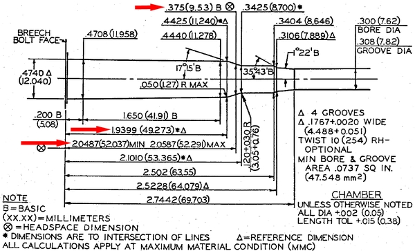
SAAMI uses a different “datum” line for the measurement than the military did. A datum line is a reference line by which the length of the gage is measured. SAAMI used one datum line, the military used a different line. This often leads to confusion about the differences between the two measurements. However, if we look at the SAAMI drawing for the 30-06 Springfield chamber we’ll see that both are in agreement.
The military used the chamber shoulder as its datum line; SAAMI uses the point where the case shoulder tapers down to 0.375″. If we look at the image below we can see both measurements. If we use the shoulder as a datum line, we can see in the image below that SAAMI lists the dimension as 1.9399 inches. The military defined the minimum headspace as 1.9400″. These two dimensions are functionally the same.
If we move our datum line out to the reference mark used by SAMMI we can see the shoulder tapers down to 0.375″. At this location we can see a measurement of 2.0487″
All modern headspace gages will use the SAAMI datum line. Should you find surplus military gages they will use the military datum line. Both are measuring the same thing but from different points along the chamber.
The two major brands of headspace gages made today are from Forster products and Clymer Tools. Both companies use the SAMMI specification and both use the same datum point. Both gages are functionally identical.
Another advanced headspacing topic is known as the delta-L problem. The subject is outside of the scope of this article and deals with conflicting specifications for the 30-06 cartridge. You can read about this at the following link. [The Delta-L Problem]
How to measure Headspace:
You will need at a minimum two headspace gages. The two gages are called a “GO” gage and a “FIELD” gage. A third gage called a “NO-GO” gage is also available and used as an intermediate gage between the GO and the Field gage. Your rifle should be cleaned and not oiled or greased when performing these tests. Pay attention to cleaning the chamber and the bolt/receiver lugs.
1 Clean the rifle chamber leaving no cosmoline or other material that would affect the measurements. If you have a chamber brush, use it. Remove any other grease, oil, and cosmoline from the action, including the locking lugs on the bolt and receiver.
2Strip the bolt. [Instructions]. Clean the bolt face.
3Strip the receiver action of all operational parts.
4With the parts removed and your bolt stripped your setup should like the image below.
5Insert the GO gage gently into the chamber and install the stripped bolt into the receiver. You never want to force a headspace gage into the rifle. Never stick a headspace gage into a rifle and let the rifle slam into battery on the gage. Your setup should now look like the image below.
6Using finger pressure only, push the bolt closed. The bolt locking lug should look like the image below. The lug MUST be all the way down and contacting the receiver to pass the GO test.
7(Skip this step if you don’t have a NO-GO gage). Remove the GO gage and install the NO-GO gage. Using finger pressure only, push the bolt closed. The bolt locking lug should look like the image below. The lug MAY be all the way down and contacting the receiver. This does not yet indicate a rifle with excessive headspace. On a NEW barrel, the locking lugs will look as shown below. As headspace increases the locking lug will move down toward the receiver.
8Remove the NO-GO gage and install the Field gage. Using finger pressure only, push the bolt closed. The bolt locking lug should look like the image below. The lug MUST NOT be all the way down and contacting the receiver. If the lug touches the receiver the rifle has excessive headspace. On a NEW barrel, the locking lugs will look as shown below. As headspace increases the locking lug will move down toward the receiver.
Interpreting your results:
[My Bolt wont close on a GO gage!]
- Did you remember to strip your bolt?
- Did you verify your chamber is clean and free of obstructions?
- Did you use the correct gage?
- Is your barrel new and not yet finish reamed?
- Did you accidentally swap bolts with another Garand?
[My Bolt closed on a NO-GO gage!]
- The NO-GO gage is an intermediate gage and by itself does not indicate excessive headspace. The results of the Field test will let you know if you have an issue.
[My Bolt closed on a FIELD gage!]
- Is the bolt locking lug actually touching the receiver? See the image of the GO gage test to see what fully locked and in battery looks like.
- If the bolt lug is fully closed then your barrel/bolt/receiver combination has reached the end of its service life (In terms of headspace). You may be able to swap in a different bolt and gain back some of the lost headspace, or you can install a new barrel and have it reamed to re-establish the correct headspacing.
If the receiver lugs are excessively worn or damaged then the receiver should be replaced. Have your gunsmith inspect the weapon and you can determine what course of action is correct for you.